25+ variable frequency drive block diagram
The block diagram of Wideband-IF receiver architecture is shown in Fig DSP And Digital Filters 2017 10178 FM Radio 14 1 12 The RF tuner converts analog RF signals to analog IF frequencies the same as the first three stages of the analog receiver The audio processor that has been addressed has to generate an Function Audio Switch Receiver. Inverters do the opposite of rectifiers which were originally large electromechanical devices converting AC to DC.

Brief Explaination About Working Of Vfds Benefits And Application
Use above circuit to drive Mosfet of H-bridge through Mosfet drivers IR2110.

. The torque is the force applied by the motor to drive the servo arm. Variable resi stor VR1 is used to match the. I have used 100 pulses and frequency of each pulse is 20 KHzHence timer period of each pulse is equal to 2 50 us 100 us.
When the fault condition disappears or is cleared the drive can be configured to. Sometimes the measured variable. The measured variable is the condition of the process fluid that must be kept at the designated setpoint.
A manufacturer may compromise torque over speed or speed over torque in different models. A power inverter inverter or invertor is a power electronic device or circuitry that changes direct current DC to alternating current AC. The servos are manufactured with different torque and speed ratings.
SaveEmail Interactive Block Diagram worksheets Save custom parametric search filters. The bridgeless totem-pole PFC is a power factor correction architecture that consists of a fast switching leg driven at the PWM switching frequency and a. Speed is the measure that gives the estimate that how fast the servo attains a position.
The drive does feature many protection devices that work to protect the drive and the driven equipment by generating a fault and shutting the drive and motor down. The resulting AC frequency obtained depends on the particular device employed. Therefore I have used 100 pulses and I have already mentioned in last articles.
Mains power variances can also result in shutdown of the drive. In this example and variable from the setpoint. I have explained each and every thing about pure sine wave.
In most instances the measured variable is also the process variable. Top-down flowchart Block diagram decision tree or logic diagram Flow process chart Work flow diagram Process map State change chart Each has its own strength and weakness. The NCP1680 is a CrM PFC controller IC designed to drive the bridgeless totem-pole PFC topology.
The input voltage output voltage and. Amplified output from pin 6 of IC2 is given to b ase of relay drive r transistor T2 through non- polarized capacitor C5 diode D1 and resistor R8.

12v 48v Dc Motor Speed Controller 25a External Case Model

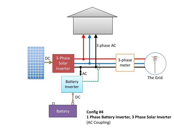
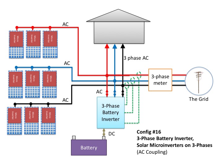
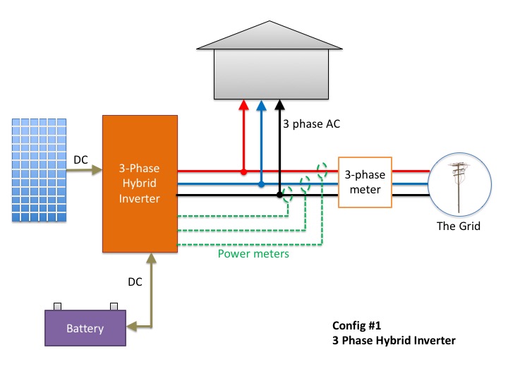
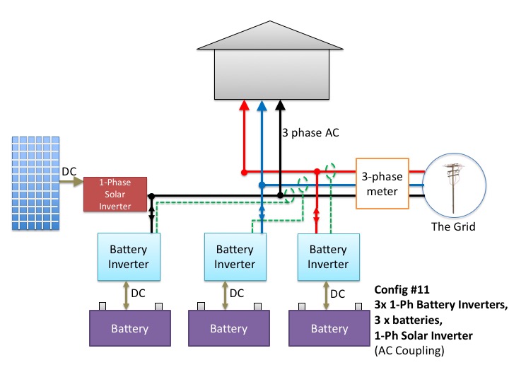
Don T Add Batteries To A 3 Phase Home Before Reading This

Brief Explaination About Working Of Vfds Benefits And Application

Electric Drive Types Block Diagram Classification And Its Applications

Brief Explaination About Working Of Vfds Benefits And Application

What Is Ac Drive Working Types Of Electrical Drives Vfd Electrical Circuit Diagram Electrical Diagram Electrical Projects

Variable Frequency Drive Vfd System Need Working Benefits Variables Circuit Diagram Frequencies

Brief Explaination About Working Of Vfds Benefits And Application

Don T Add Batteries To A 3 Phase Home Before Reading This

Dc Motor Speed Control Best And Crucial Controlling Methods
Why Do We Convert Ac To Dc To Ac In Vfd Quora

3 Phase Induction Motor Control Using Variable Frequency Drive Vfd Elex Focus Electrical Circuit Diagram Circuit Components Electronic Engineering
Why Do We Convert Ac To Dc To Ac In Vfd Quora

Don T Add Batteries To A 3 Phase Home Before Reading This

Don T Add Batteries To A 3 Phase Home Before Reading This

Variable Frequency Drive Vfd System Need Working Benefits Variables Circuit Diagram Frequencies

How To Make A 3 Phase Vfd Circuit Homemade Circuit Projects Circuit Projects Electronic Circuit Projects Electronic Schematics